The H-J Family
of Companies
of Companies
Use:
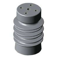
200 Series Uniform Strength Switch and Bus Insulators are available for outdoor and non UV exposed (enclosed) applications.
200 Series insulators are available for 5 kV through 46 kV voltage classes. 200 Series insulators are used primarily as bus supports in switchgear applications,
dry type transformers and other custom applications.
Construction:
200 Series Uniform Strength Switch and Bus Insulators are precision engineered to ANSI C29.1-1988 specifications
using state of the art Finite Element Analysis (FEA) software.
200 Series insulators are of cast epoxy construction with metallic mounting inserts integrally cast into the unit.
Through use of an integrally cast insert, the need for metallic end caps fixed with adhesives is eliminated.
Adhesives tend to deteriorate over time causing future partial discharge concerns.
This problem is most often associated with porcelain insulator designs.
200 Series insulators’ conical design provides mechanical loading characteristics superior to most polymer insulator designs in the market today.
Mounting configurations are NEMA standard and may comprise of up to 100 different variations.
The deep shed design offers generous creep distances.
The epoxy material is lightweight compared to porcelain, and is self extinguishing when exposed to continuous arcing or constant heating.
Units at 95 kV BIL or greater, with more than two mounting inserts per end, are tied internally to prevent floating of inserts not used.
| Identification No. | Dimensions | Strength Class (NEMA) | Creep Distance (in) | Electrical Ratings | Mechanical Ratings | |||||
|---|---|---|---|---|---|---|---|---|---|---|
| DIA. (in) | Height (in) | Highest System Voltage (kV) | Impulse Voltage (kV) | 60 HZ Withstand 1 min (kV) | Cantilever (lbs) | Tension (lbs) | Compression (lbs) | |||
| 02-000 | 4.00 | 3.50 | A20 | 4.53 | 4.8 | 60 | 19 | 3000 | 3000 | 40000 |
| 02-001 | 4.00 | 4.50 | A20 | 6.41 | 8.3 | 75 | 26 | 2250 | 3000 | 40000 |
| 02-002 | 4.00 | 6.00 | A20 | 9.79 | 15.0 | 95 | 36 | 1750 | 3000 | 40000 |
| 02-003 | 4.00 | 7.50 | A20 | 12.26 | 20.0 | 110 | 50 | 1400 | 3000 | 40000 |
| 02-004 | 4.00 | 8.75 | A20 | 15.51 | 25.0 | 125 | 60 | 1200 | 3000 | 40000 |
| 02-005 | 4.00 | 10.50 | A20 | 19.1 | 38.0 | 150 | 80 | 1000 | 3000 | 40000 |
| 02-006 | 4.00 | 11.00 | A20 | 19.55 | 38.0 | 150 | 80 | 950 | 3000 | 40000 |
| 02-007 | 4.00 | 12.75 | A20 | 22.13 | 38.0 | 170 | 80 | 850 | 3000 | 40000 |
| 02-008 | 4.00 | 14.00 | A20 | 25.17 | 48.3 | 200 | 100 | 750 | 3000 | 40000 |
Uniform Strength Switch & Bus Insulators are tested in accordance with ANSI C29.1-1988.
Mechanical ratings, based on static loading applied in a practically stepless variation, are provided for
design purposes and are considered safe for all insert configurations.
Actual values attainable will vary with each application and type of loading condition.
Impulse wave 1.2 x 50 µS.
Frequency 60 Hz.
| 000 | 001 | See 001 | 002 | See 002 | 003 | 004 | |
| 005 | 006 | 007 | 008 | 009 | 010 | 011 | |
| 012 | 013 | 014 | 015 | 016 | 017 | 018 | |
| 019 | 020 | See 020 | 021 | See 021 | 022 | 023 | |
| 024 | 025 | See 025 | 026 | See 026 | 027 | 028 | |